
process and instrumentation diagram for cement plant manufacturer Grasping strong production capability, advanced research strength and excellent service, Shanghai process and instrumentation diagram for cement plant supplier create the value and bring values to all of customers.
 WhatsApp)
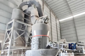
Aug 30, 2012· Generally cement plants are fixed where the quarry of limestone is near bye. This saves the extra fuel cost and makes cement somehow economical. Raw materials are extracted from the quarry and by means of conveyor belt material is transported to the cement plant. There are also various other raw materials used for cement manufacturing.
Feb 13, 2017· The process flow of any asphalt plant will depend on the type of the plant. Right now we have different types of asphalt mixer available in the market. These mixers are build keeping in mind different customer types. There are two major types / categories: batch type and continuous type. Batch type: With this design the production of hot mix will be done in batches .
Jul 11, 2020· A Process and Instrumentation Diagram (P ID) shows the process flow and interconnection of process equipment which is used control a process. The P ID includes every mechanical aspect of the plant except stream flows, pipe routing, pipe lengths, pipe fittings, supports, structure foundations.
The Plant SDK provides development tools for both AutoCAD® PID and AutoCAD® Plant 3D software. AutoCAD PID software allows you to create, modify, and manage schematic piping and instrumentation diagrams. AutoCAD Plant 3D adds 3D models, including piping, equipment, support structures, generation of isometric, and orthographic drawings.
Aug 17, 1971· sixdigit SCC for plants with dry process kilns is 305007. Portland cement accounts for 95 percent of the hydraulic cement production in the United States. The balance of domestic cement production is primarily masonry cement. Both of these materials are produced in portland cement manufacturing plants. A diagram of the process, which
A Process and Instrument Drawing (PID) includes more details than a PFD. It includes major and minor flows, control loops and instrumentation. PID is sometimes referred to as a Piping and Instrumentation Drawing. These diagrams are also called flowsheets. PIDs are used by process technicians and instrument and electrical, mechanical, safety ...
A piping and instrumentation diagram (PID), sometimes called piping flow diagram or process flow diagram, is a kind of schematic drawing, which shows the sequence of process equipments and instrumentations. PID is used for erection and commission as well as during maintenance of a process plant.
b) Piping and Instrumentation Diagram (P ID) (mechanical flow diagram) A PID diagram shows the arrangement of the process equipment, piping, pumps, instruments, valves and other fittings. It should include: All process equipment identified by an equipment number.
Process Instrumentation Services To remain competitive, companies in industry must ensure – and ideally increase – the availability and productivity of machines and plants. As your partner, we offer a unique range of services and support based on our extensive technology and industry expertise.
Process and Instrumentation Diagram Development. In Water and Waste Water Treatment Plants. Steven J. Marrano, Instrumentation and Controls Engineer. The process and instrumentation diagram ("PID" as it often called) represents a document that can take on many different forms depending upon the following factors:
An outline of key instrumentation is shown on Process Flow Diagrams (PFD) which indicate the principal equipment and the flow of fluids in the plant. Piping and Instrumentation Diagrams (PID) provide details of all the equipment (vessels, pumps, etc), piping and instrumentation on the plant in a symbolic and diagrammatic form.
Oct 22, 2015· Cement Plant Process and Instruments Used 1. Plant Process Instruments Used Ravi Roy DeptInstrumentation 2. What is cement? The term cement is commonly used to refer to powdered materials which develop strong adhesive qualities when combined with water.
Cement manufacturing process components of a cement plant from quarry to kiln to cement mill. 1A Manufacturing Process for Iron and Steel After the BFBOF process, molten steel is controlled to a target composition and temperature and is then cast by continuous casting machine to produce slabs, blooms, and billets.
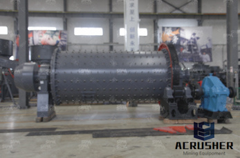
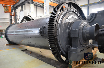
process and instrumentation diagram for cement plant process and instrumentation diagram for instrumentation in cement plant lvdivseacadetsorg process, Cement plantChina Machinery Cement plant includes the vibrating feeder, jaw crusher, impact crusher, cement ball mill, lifer, preheating system, cement rotary kiln and packing machine and so on
Jun 23, 2020· A Definition of PID A piping and instrumentation diagram (PID) is a drawing in the process industry. A PID shows all piping, including the "physical sequence of branches, reducers, valves, equipment, instrumentation and control interlocks." A PID is used to operate the process system, since it shows the piping of the process flow along with .
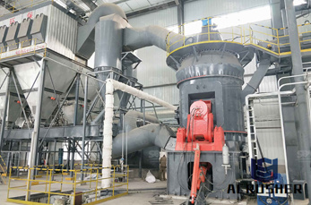
Detailed Process Diagrams Our robust, dependable solutions for process instrumentation, weighing, and process analytics deploy the highest precision to help you keep processes under control in even the roughest conditions. Use our process charts to find the right solution for your application. ... Cement Plant. The hidden qualities of kiln dust
Learn How to Read Piping and Instrument DiagramPID, Process Flow Diagram and Block Flow Diagram used in Process Plant (359 ratings) Course Ratings are calculated from individual students'' ratings and a variety of other signals, like age of rating and reliability, to ensure that they reflect course quality fairly and accurately.
Efficiently manage all your instrumentation and motor data with the software''s fully integrated relational database. Ensure consistency in your process plant control system design with the automatic creation of instrumentation data sheets and specification sheets.
A piping and instrumentation diagram (PID) is a detailed diagram in the process industry which shows the piping and process equipment together with the instrumentation and control devices.. Superordinate to the PID is the process flow diagram (PFD) which indicates the more general flow of plant processes and the relationship between major equipment of a plant facility.
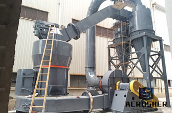
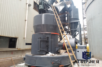
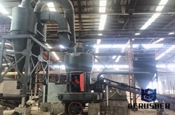
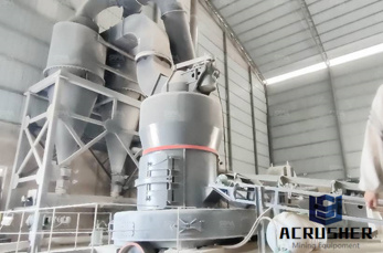
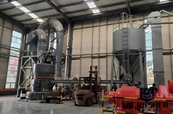
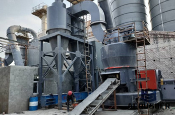
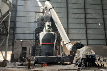
This cement plant operates on a dry process line with a fi vestage suspension preheater and an inline precalciner. The kiln is 4 m in diameter and 60 m in length.
Jan 27, 2020· PIDs, or Piping and Instrumentation Diagrams to give them their full name, are schematic representations of pipelines, equipment, instrumentation, and control systems found in process environments such as Oil Refineries, Chemical Plants, Paper Mills, and Cement Plants, etc.
Jan 27, 2020· PIDs, or Piping and Instrumentation Diagrams to give them their full name, are schematic representations of pipelines, equipment, instrumentation, and control systems found in process environments such as Oil Refineries, Chemical Plants, Paper Mills, and Cement Plants.
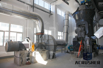
A development of this process is the ''precalciner'' kiln. Most new cement plant is of this type. The principle is similar to that of the dry process preheater system but with the major addition of another burner, or precalciner. With the additional heat, about 85%95% of .
Process And Instrumentation Diagram Of Cement Plant. . (Mechanics + Control Instrumentation) . spain ball mill mining. instrumentation and control, circuit diagrams in .
WhatsApp)